|
|

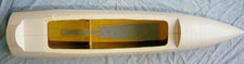
The fuselage is molded in two part, the nose section and the main body, this is to help with construction and transportation as the nose is removable. The nose and main body sections are mated and joined with 6/32 screws and blind nuts.
F14A Tomcat Construction Notes
| The Tomcat comes in two large boxes with lot of packing, all small parts are put into bags to help with identifying components which is very nice. I kind of jumped around the manual when I was building so I recommend that you go through your manual a few times yourself so you can make building adjustments during your own construction. The first thing I did was to wash off any release agent that still may be left from the molding process, this can be done with warm soapy water. |
The fuselage is molded in two part, the nose section and the main body, this is to help with construction and transportation as the nose is removable. The nose and main body sections are mated and joined with 6/32 screws and blind nuts. |
|
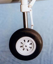
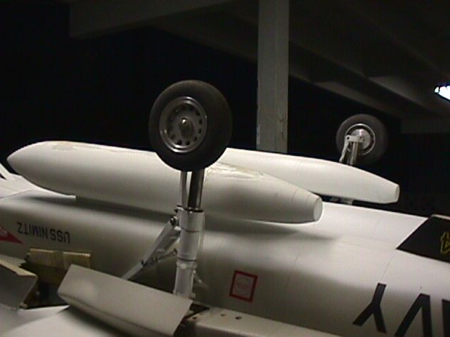
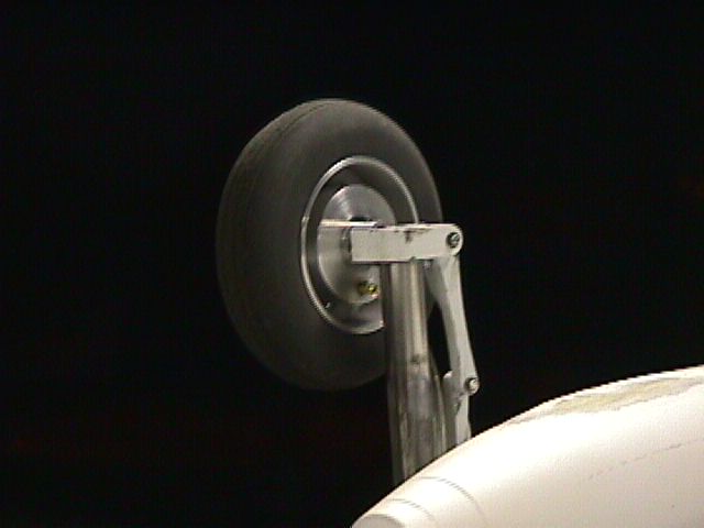
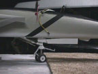
A
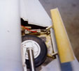
small note with the wheels supplied. They are Robart 3.5 inch mains, the
nose are Dubro 2 inch wheels. The nose wheels are fine, the mains have a
problem being that they cannot support the weight of the Tomcat. No one
makes wheels specifically for this bird. Glennis
Aircraft makes wheels for the Yellow Aircraft 1/9 scale Tomcat but
not this one. I have ordered a set of their EconoJet 3.5 inch wheels to
evaluate them as far as a retro fit for the DCU kit. I am confident I
will be able to fabricate a adapter or something to get them to work
properly. **NOTE** - I have gotten the Glennis wheels to work
superbly! With no real modifications at all! Now, I have the gear
pictured to the left/down, DCU now makes slightly different gear which is
better as far as actuation is concerned. So I can't really say it would
be the same for you if you have the new ones.
If you rather not spend another $220 dollars, which I would suggest doing, I have had success with using certain rubber/foam type materials placed within the tire themselves, the key is to find the right material to do so. I have been using material from a Rubber Slipper ( we locals in Hawaii are famous for wearing slippers everywhere). It was thin so I glued them together with GOOP. I then made a wood dowel spindle to turn the foam and shape it into a donut as to fill the tire inside completely. I used sand paper ( 40 - 80 grit) to shape the donut. They then can be stuffed into the tire, it will easily support the weight of the plane then. I went flying today (2/21/99) with this mod to the tires and it worked fine. Just look around your home to find stuff or the local hardware store. |
|
The MOST
IMPORTANT THING WHEN CONSTRUCTING THIS PLANE!
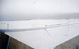
When constructing the wings and you are aligning them, be sure they are
as close to perfect as you can get, my wings are within 1/16 of a inch
of each other, wings out and wings back, and I have no problems with
roll trim when flying wings out or swept. What ever the difference is
with the wings out, make sure that difference is the same with the wings
swept. That's so you won't have surprises when the wings are swept back
( roll trim changes). |
|
|
|
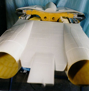
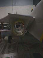
Grind out all the usual holes in the fuselage and
leave about 1/16 inch for any gear door steps you may need same goes for
the intake too but with about 1/8 on the bottom lip. The main
landing gear may require almost all of the step removed in some areas.
The inlet holes need to be removed as well. The bottom of the inlet has
a slighter larger radius than the sides do so leave a little more
material there. The inlets can be glued in place after the wings and
landing gear block is finalized.
If you already checked your wing sweep previously like I did, you will only need to verify one more time that everything is cool before gluing in the rear landing gear blocks. check with the maintenance page for further updates in this area. |
|
|
| Wings, Vertical Fins/Rudder and Horizontal Stabs are pretty much done is the conventional manner no surprises here at all. When attaching the Vertical Fins to the aircraft, pay attention o the 5 degree slant on them. Also, I installed a couple of 1/4 inch dowel pegs to allow for extra purchase on the joint and help with any possible load on the vertical fin spar. I used BVM AeroPoxy with a 12 inch flexible nylon sleeve ( as a extension tip) to help beef up the area near and around the vertical fin spar section. It is rather thin back there so after I laid in a fillet on the bulkhead/fuselage joint, I glass over the section with 2 oz cloth and epoxy to make sure its tied down good. It didn't add much weight, but will greatly increase the stiffness of the area and provide more reassurance in an already-hard-to-reach-to area. * Check the maintenance page for a update here! |
|
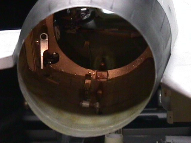
| Install
the Dynamax Custom fan mounts supplied with the kit. Dynamax* is THE fan
to use, do not use the Ramtec, or anything else. Besides, the fan
mounts are made for Dynamax anyway.
Make sure when attaching the Custom fan mounts to the Dynamax fan shrouds that you slightly counter sink the holes that you drill to help relieve stress. Any holes that you make could end up splitting or cracking if this is not done. I changed the fuel cells and used two Dubro 20 oz. tank instead of the two 16oz. tanks supplied. I also changed the hopper tanks, went from two 6oz. tanks going to two 4oz., the idea with that is to free up some space in the engine compartment. All the plumbing is of the Large fuel tubing /brass setup, standard stuff. Only from the needle valve back to the engine is the smaller (medium) line. I used Prather (pink) fuel line for this one as it is a little stiffer. The instruction mentions pipe pressure, I opted for Pitot power, in this case the Ramtec/Trim Aircraft Pitot. I changed the Rudder Servo location and linkage. It originally called for one servo, positioned between the engines, to drive two rudders. Due to the angle involved with this setup, the linkage had acquired too much slop for my taste. I positioned a Hitec 205 BB servos about a 2 inches behind the main retracts on each side of the plane. A Sullivan Semi-Flexible Cable was used to provide linkage between the servo and rudder horn. This tucked in nicely over the thrust duct. I also used Robart Pin Hinges instead of the method described in the manual for a more secure hinge joint with less possibility of flutter. Most everything else in the plane is rather straight forward with nothing complicated. You will run out of space quickly so getting in there to do maintenance or repairs would be hard without a little planning as to where you equipment will go. |
 |
 |
The one thing I knew I was going to do from the get go was gear doors. Most people leave them, out but I had to have em! Unfortunately, DCU didn't put any instructions for them in the manual, but basically it comes down to what works for you. I got kind of cheap doing the main gear doors but if I had spent another $40 dollars then it would have saved me some time. I ended up using 4 BVM short stroke air cylinders and 2 Century air cylinders (which were just laying around and will be replace soon), UEI Hidden Hinges ( included with kit), 2 Dubro bellcranks, some EZ connectors, some 40# test Nylon coated steel leader ( fishing leader) and a small pull spring. For actuation I used a Robart air valve assembly. This is all tied together with the Jomar Electronics Gear and Door Sequencer. |
 |
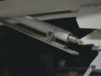 |
| I
replaced the original Wing Sweep power connectors with the new Deans
connectors. They have much better contact and are a little smaller than
the bulky original bullet unit. The wire leading from the unit to the
battery was also changed to a multi-stranded 14 gauge wire used for RC
cars. Note! You should check the capacitor periodically
to make sure it is attached properly to the motor drive.
If I were to reconstruct the Tomcat, a modification I would make is to change the Elevon Pivot Arm and Elevon shaft. I would fabricate a new arm and shaft with a pin or set screw to go through the shaft. The shaft currently has teeth on the end on which the pivot arm clamps onto, which works completely fine. The problem with this is that the Elevon shaft assembly (with the teeth) will not pass through the pivot housing for removal. Just food for thought. I mean, if you are not going to take it on trips and have to haul it around long distance then it is perfectly fine the way it is. |
| There
is really nothing else really special or weird when building the Tomcat.
Optional fuel tanks ( non functional) are available from DCU, they are
about $125 dollars for the pair with pylons. If you are thinking about
putting them on, I used blind nuts tucked in under the intake ducts and
4-40 bolts to secure the pylons and a vortac bomb release unit to
conveniently remove the tanks when I am not flying with them. They look
great and would suggest getting them.
|
|
Questions? email CAG |